Project overview
STM32F1-LCD16032 drives a WG16032D3 graphic LCD (160x32 pixels, ST7920 controller) from an STM32F103C8Tx. The project is generated with CubeMX/HAL for STM32CubeIDE and drives the display through the 8-bit parallel interface using plain GPIO.
There are two ways to show content:
- Built-in text mode - a minimal driver in
Core/Src/ST7920.cwrites characters into the controller's text RAM using the display's own font. - u8g2 mode - the u8g2 graphics library (in
Middlewares/u8g2) with a frame buffer, fonts, lines and UTF-8 text, enabled with theU8G2macro inCore/Src/main.c.
Hardware pinout (STM32F103C8Tx -> WG16032D3)
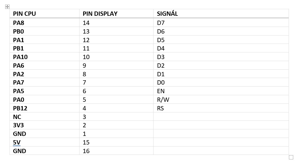
Pin mapping from STM32F1-LCD16032.ioc:
| LCD signal | STM32 pin | Note |
|---|---|---|
LCD_DB0 |
PA7 |
data bit 0 |
LCD_DB1 |
PA2 |
data bit 1 |
LCD_DB2 |
PA6 |
data bit 2 |
LCD_DB3 |
PA10 |
data bit 3 |
LCD_DB4 |
PB1 |
data bit 4 |
LCD_DB5 |
PA1 |
data bit 5 |
LCD_DB6 |
PB0 |
data bit 6 |
LCD_DB7 |
PA8 |
data bit 7 |
LCD_RS |
PB12 |
register select |
LCD_RW |
PA0 |
read/write, held low (write only) |
LCD_EN |
PA5 |
enable strobe |
| SWD | PA13 / PA14 |
programming and debug |
The ST7920 is in parallel mode when its PSB pin is pulled high. The wiring photo and the display datasheets are in Documents/.
Clock and peripheral configuration
- External HSE oscillator on
PD0/PD1, PLLx9 SYSCLK = HCLK = 72 MHz,APB1 = 36 MHz- USB clock
48 MHzfrom the PLL (/1.5prescaler) TIM1with internal clock, used as a microsecond time base- All LCD pins are GPIO outputs with high speed
Firmware modules
1) Delays (Core/Src/delay.c)
HAL_Delay_us() and HAL_Delay_ms() busy-wait on the TIM1 counter. Delays longer than the 16-bit counter range are split into several steps. The ST7920 needs delays in the tens of microseconds, which HAL_Delay() cannot provide.
2) ST7920 driver (Core/Src/ST7920.c)
LCD_WriteCmd()/LCD_WriteData()setRS, put one byte onDB0..DB7and strobeENwithDELAY_LCD_EN_US(10 us); changingRSaddsDELAY_LCD_RS_US(50 us)LCD_Init()runs the initialisation sequence: function set0x30twice, display on0x0C, clear0x01, entry mode0x06LCD_PutStr(x, y, text)sets the DDRAM address and writes a string in the display's built-in font
3) u8g2 integration
u8g2_gpio_and_delay_stm32() is the u8g2 callback that maps u8x8 messages (GPIO_D0..D7, GPIO_E, GPIO_DC, delays) to the GPIO pins and the delay functions. The display is set up with u8g2_Setup_st7920_p_192x32_f() and u8x8_byte_8bit_6800mode, which uses the frame buffer.
The example in main.c draws horizontal lines and three lines of text with the u8g2_font_6x12_te font, including Czech diacritics, then sends the buffer with u8g2_SendBuffer().
Build, flash, and test
- Open the
STM32F1-LCD16032project in STM32CubeIDE - Choose the mode in
Core/Src/main.c:#define U8G2 0for built-in fonts,1for u8g2 - Build and flash through ST-LINK (SWD on
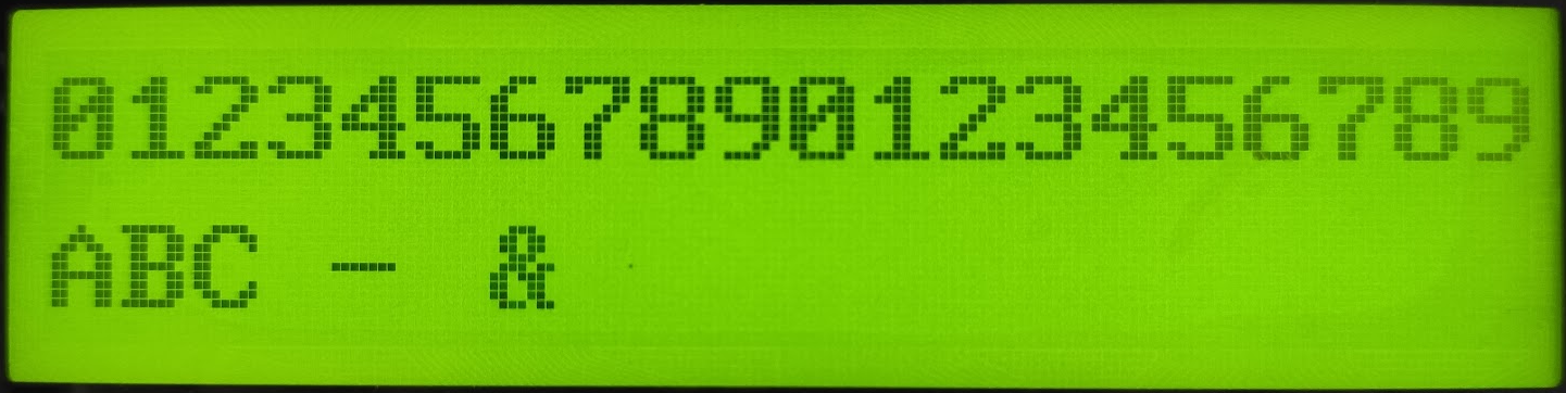
PA13/PA14) - Wire the display as in the table above. In built-in mode the second line shows an incrementing character every 200 ms; in u8g2 mode the test text and lines appear
Notes
- The u8g2 setup uses the 192x32 ST7920 variant; the visible area of the WG16032D3 is 160x32 pixels
- Delay constants in
ST7920.cwere tuned for this display and may need to be longer for other modules - Display documentation:
Documents/WG16032D3.pdf,Documents/GLCD/ST7920.pdf
Images